


| Issue |
EPJ Photovolt.
Volume 17, 2026
Special Issue on ‘Recent Advances in Photovoltaics 2025, edited by Marie Gueunier Farret, Judikaël Le Rouzo and Thomas Fix’
|
|
|---|---|---|
| Article Number | 28 | |
| Number of page(s) | 14 | |
| DOI | https://doi.org/10.1051/epjpv/2026021 | |
| Published online | 22 July 2026 | |
https://doi.org/10.1051/epjpv/2026021
Original Article
Numerical investigation of passive cooling strategies for photovoltaic modules using recycled polyurethane foam and aluminum fins
1
Univ Paris Est Creteil, CERTES, Creteil, F-94010 France
2
Laboratory for the Studies of Ionized & Reactive Media (EMIR), University of Monastir, Monastir 5000, Tunisia
3
Laboratory of Energy Applications and Renewable Energy Efficiency (LAPER), University of Tunisia El Manar, Tunis 1068, Tunisia
4
ISSAT of Sousse, Energy Department, University of Sousse, Sousse 4011, Tunisia
* e-mail: This email address is being protected from spambots. You need JavaScript enabled to view it.
Received:
19
March
2026
Accepted:
25
June
2026
Published online: 22 July 2026
Abstract
This work presents a numerical study of two passive cooling strategies for photovoltaic (PV) modules using recycled materials. The main goal is to limit the performance losses caused by high operating temperatures under real outdoor conditions, which differ significantly from Standard Test Conditions (STC), and to improve the overall electrical efficiency. The analysis is performed using three-dimensional transient simulations in COMSOL Multiphysics, coupling heat transfer and fluid flow in solid and porous domains. In the first configuration, a recycled polyurethane (PU) foam layer saturated with water is applied at the rear of the PV module to enhance heat dissipation through coupled heat and moisture transport within the porous structure, including evaporative cooling effects. The second configuration uses aluminum fins attached to the rear surface of the module, increasing the heat exchange area and strengthening natural convection with ambient air. The results show that the PU foam and aluminum fin systems reduce the average operating temperature by 16.4 °C and 9.8 °C, respectively, compared with the reference module. These reductions translate into relative electrical efficiency improvements of 8.49% and 5.10%, confirming the effectiveness of both passive cooling approaches under the studied conditions.
Key words: Photovoltaic modules / passive cooling / evaporative cooling / recycled materials / polyurethane foam / thermal management
© M. Almazhoud et al., Published by EDP Sciences, 2026
 This is an Open Access article distributed under the terms of the Creative Commons Attribution License (https://creativecommons.org/licenses/by/4.0), which permits unrestricted use, distribution, and reproduction in any medium, provided the original work is properly cited.
1 Introduction
The global energy sector is currently undergoing a major transition driven by the urgent need to reduce greenhouse gas emissions and ensure sustainable energy supply. With continuous population growth and industrial development, global energy demand is expected to increase significantly in the coming decades. In this context, renewable energy solutions have become essential to ensure long-term energy security while reducing environmental impacts [1] and their adoption has been driven by technological advancements and increasing concerns over the environmental impact of fossil fuels [2].
Within green energy solutions, photovoltaic (PV) systems are widely used and have shown strong growth in recent years [3]. However, their performance is significantly affected by operating temperature [4]. Approximately 80–90% of incident solar radiation is converted into heat, which increases module temperature and reduces electrical efficiency [5].
This temperature rise mainly reduces the open-circuit voltage (VOC), while the short-circuit current (Isc) is only slightly affected [6,7]. PV efficiency typically decreases by 0.125% to 0.75% per 1 °C increase in temperature [8], which makes thermal management essential for improving performance.
To reduce these losses, several cooling methods have been proposed in the literature [9]. These techniques are generally classified into active and passive systems [10]. Active cooling approach such as forced air cooling [11], water circulation [12], and nanofluids [13] provide high heat removal capability, but require external energy input, which increases system complexity and reduces net efficiency.
In contrast, passive cooling strategies have attracted increasing attention due to their simplicity, low cost, and zero parasitic energy consumption [14]. These methods rely on natural heat transfer mechanisms, including conduction, convection, radiation, and evaporation. PV temperature can be controlled using several passive cooling approaches, such as thermoelectric cooling [15], phase change materials (PCM) [16], liquid immersion [17] and radiative cooling [18].
Among passive approaches, evaporative cooling has demonstrated strong potential for PV thermal regulation. Arivazhagan et al. [19] reported that water film cooling can reduce the temperature of the PV module by 8–12 °C, leading to power output improvements of 11–23% and efficiency gains of 13.3–26%. Similarly, wick-based evaporative systems combined with fins have been shown to achieve temperature reductions of up to 20 °C, with average electrical performance improvements of 11.2% [20]. Hybrid configurations such as PV–solar still systems have also demonstrated temperature reductions of about 8 °C, resulting in electrical output improvements of 10% [21]. In addition, Chea et al. [22] developed a collector-based model for rear-side evaporative cooling using water flow, confirming improved thermal behavior and an overall performance enhancement of 4.7%.
Porous media cooling is another effective passive strategy. It enhances heat transfer through conduction, fluid transport, and diffusion within the porous structure. A hybrid porous media–water system applied to a 30 W PV module achieved a temperature reduction of 27% (50.9 °C to 37.7 °C), together with improvements in the power output (12.3%) and efficiency (13.5%) [23]. Numerical studies on concentrated PV/T systems with porous heat sinks have also reported severe thermal loads under high porosity conditions, highlighting the importance of efficient porous thermal management [24].
Additionally, heat sink-based cooling, particularly aluminum fins, remains widely used due to its high thermal conductivity, low cost, and simple fabrication process. Experimental investigations [25] reported a PV temperature reduction of approximately 4.2 °C with an efficiency improvement of about 5%. In addition, other studies have shown temperature reductions of up to 7.5 °C together with an increase in the open-circuit voltage under different operating conditions [26].
Despite these developments, most studies focus on a single cooling technique under specific conditions. Few works provide a direct comparative analysis of different passive cooling strategies using a consistent numerical framework. Moreover, the use of recycled materials in PV thermal management remains limited in the literature.
In this study, two passive cooling approaches for PV modules are numerically investigated using COMSOL Multiphysics under identical environmental conditions. The first approach consists of a water-saturated recycled polyurethane (PU) foam layer to enhance evaporative cooling via porous media effects. The second employs a simplified aluminum fin design to promote natural convection and increase the effective heat transfer area. Both approaches are evaluated against a reference uncooled PV module in terms of thermal behavior and corresponding electrical performance.
The main contribution of this work is a comparative numerical assessment of two sustainable passive cooling strategies under identical operating conditions, highlighting the trade-off between evaporative porous cooling and fin-based convective enhancement. The use of recycled materials further emphasizes the environmental relevance of the proposed solutions.
The remainder of this paper is organized as follows: Section 2 presents the numerical modeling approach. Section 3 discusses the simulation results. Section 4 compares the findings with previous studies. Finally, Section 5 concludes the paper.
2 Numerical modeling approach
This section presents the numerical model developed for the photovoltaic module and the two passive cooling configurations. It describes the geometry, cooling designs, boundary conditions, meshing strategy, and modeling assumptions, including the evaporative cooling case, as well as the governing physical processes.
The simulations were conducted using COMSOL Multiphysics, selected for its capability to solve coupled Multiphysics problems involving heat transfer, fluid flow, and porous media transport within a unified finite-element framework. This allows accurate representation of the coupled thermal and fluid-dynamic behavior governing the passive cooling systems.
2.1 Modeling of the photovoltaic panel
Figure 1 presents the cooling materials used as the basis for the numerical model, namely polyurethane (PU) foam and the aluminum fin structure.
The geometric configurations of the PV module, including the reference panel and the two passive cooling configurations, are illustrated in Figure 2. The PV module is modeled as a rectangular plate with dimensions of 82 cm × 80.8 cm and a total thickness of 0.6 cm, composed of a 0.2 cm silicon layer and a 0.4 cm glass layer. The junction box is represented as a simplified rectangular component with dimensions of 10 cm × 10 cm × 1.4 cm.
For the evaporative cooling configuration, a 0.5 cm thickness PU foam layer is applied on the rear surface of the PV module while preserving the original geometry, ensuring full coverage and effective thermal contact. The foam is assumed to remain fully saturated with water throughout the simulation to evaluate the impact of the evaporative cooling on the heat dissipation and the electrical performance.
For the aluminum fin configuration, the complex geometry of the recycled fins is simplified into an equivalent arrangement of 29 horizontal rectangular fins to reduce computational cost. Each fin has dimensions of 15 cm × 10 cm × 0.5 cm, with a spacing of 2 cm between adjacent fins. This simplified representation preserves the main geometric parameters governing heat transfer, including fin dimensions, spacing, and thermal contact with the rear surface of the PV module. This approximation is justified by the objective of the present study, which focuses on the overall thermal performance of the cooling system rather than local flow details around individual fins. It allows the dominant on the heat transfer mechanisms to be accurately captured while maintaining computational efficiency.
Table 1 summarizes the electrical specifications of the PV module, while Table 2 reports the thermophysical properties of the materials used in the simulations.
The computational domain is discretized using the physics-controlled meshing tool available in COMSOL Multiphysics, which automatically generates an optimized tetrahedral mesh based on the simulation requirements. The mesh is refined in regions with strong thermal gradients, particularly near the PV surface and the cooling configurations. A mesh independence study has been conducted to ensure that the numerical results are not affected by grid resolution. Three mesh levels were considered: coarse, medium, and fine. The effect of mesh refinement was evaluated for all configurations (Standard panel, Foam-Cooled, and Fin-Cooled) using key output parameters, including the average PV temperature, the maximum PV temperature, and the electrical power output (Tab. 3).
The results indicate that the solution is weakly sensitive to the mesh refinement. The differences between the medium and fine meshes are negligible for all variables, with relative deviations generally below 1%, confirming mesh independence.
Based on this analysis, the medium mesh is selected as the reference discretization for all simulations, as it provides an optimal compromise between numerical accuracy and computational cost while ensuring stable and reliable results.
The mesh generation parameters and the resulting mesh statistics are summarized in Tables 4 and 5, respectively, while the generated mesh for the PV module configurations is illustrated in Figure 3. In addition, the simulation results were recorded at 30-minute intervals, which provides sufficient temporal resolution to capture the system dynamics while avoiding the excessive data storage requirements.
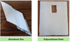 |
Fig. 1 Photographs of experimental components used as reference for numerical modeling. |
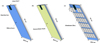 |
Fig. 2 Schematic representation of the modeled photovoltaic (PV) configurations: (a) Standard Panel, (b) PU Foam-Cooled Panel, (c) Fin-Cooled Panel. |
Mesh independence study results.
Mesh characteristics.
Mesh characteristics of the simulated configurations.
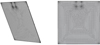 |
Fig. 3 Mesh layout of the PV module. |
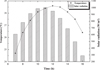 |
Fig. 4 Temporal evolution of ambient temperature and solar irradiation. |
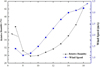 |
Fig. 5 Variations of the ambient humidity and wind speed over time. |
2.2 Boundary conditions
Transient simulations were performed using time-dependent meteorological data for Monastir, Tunisia (22 May), including solar irradiance, ambient temperature, wind speed, and relative humidity (Figs. 4 and 5). The solar irradiance varies from 608 W.m−2 at 7:00 h to a maximum of 1001 W.m−2 at 11:00 h, followed by a gradual decrease during the afternoon. This time-dependent profile is applied as a surface heat flux on the front glass layer of the PV module.
The incident solar radiation is implemented as a surface heat flux applied on the front glass surface of the PV module, representing the absorbed portion of the incoming solar irradiance. This formulation ensures that the solar energy input is treated strictly as a boundary heat source. The absorbed solar radiation is expressed as:
 (1)
(1)
where α is the absorptivity coefficient, equal to 0.85 and I(t) is the time-dependent solar irradiance.
Convective heat transfer is modeled using Newton’s law of cooling. The ambient temperature is imposed as a time-dependent boundary condition varying between 24.7 °C and 28.6 °C. The convective heat transfer coefficient is defined as a function of wind speed, introduced as a time-dependent environmental parameter with an average value of 2.14 m.s−1, allowing the model to capture both natural and forced convection effects under realistic operating conditions.
Radiative heat exchange between the PV surfaces and the environment is modeled using a surface-to-sky radiation approach. A constant emissivity is assumed for the PV module, and the sky temperature is estimated using the empirical correlation: Tsky = 0.0552 Tamb1.5 [29], which is widely used in the literature as a practical approximation in the absence of detailed atmospheric radiation data.
The role of the relative humidity is particularly important in the PU Foam Cooling configuration. In this study, the relative humidity is introduced as a time-dependent environmental parameter obtained from meteorological data and imposed at the foam–air interface. It governs the evaporative cooling process through the vapor pressure difference between the saturated foam surface and the surrounding air, which acts as the main driving force for interfacial mass transfer. Consequently, variations in the relative humidity directly influence the evaporation intensity and the resulting cooling performance.
All simulations are conducted under fully transient conditions using coupled thermal boundary conditions to ensure a realistic representation of the behavior of the PV system.
2.3 Modeling assumptions and evaporative cooling configuration
The numerical model is developed based on a set of simplifying assumptions to ensure computational efficiency while preserving the dominant physical mechanisms governing the behavior of the system. The PV module is modeled as a multilayer structure composed of homogeneous and isotropic materials with temperature-independent thermophysical properties over the simulation period. Perfect thermal contact is assumed between adjacent layers, and interfacial thermal resistance is neglected.
The surrounding airflow is assumed to be incompressible and laminar, while buoyancy-induced flow is accounted for using the Boussinesq approximation to model the natural convection effects. Surface fouling phenomena, including dust accumulation, are not considered. Transient simulations are performed using time-dependent meteorological data to reproduce realistic outdoor operating conditions.
The PU foam layer is assumed to remain continuously saturated with water throughout the simulation. This assumption represents a practical operating condition commonly adopted in porous evaporative cooling systems. It is ensured by a passive water supply mechanism, such as capillary action or a reservoir-fed system, which compensates for the evaporation losses and maintains continuous wetting of the porous medium during operation.
Under this assumption, the evaporation rate, the water consumption, the and drying behavior are not explicitly modeled, as their accurate representation would require a fully coupled multiphase heat and mass transfer formulation involving liquid transport, vapor diffusion, and phase change processes, which is beyond the scope of this study.
The effect of the humidity is reflected through the vapor pressure gradient between the saturated foam and the surrounding air, which governs the evaporation process and controls the moisture exchange at the foam–air interface.
2.4 Description of the physical processes
Figure 6 illustrates the heat transfer mechanisms occurring within the PV module under solar irradiance for the two passive cooling configurations are investigated in this study.
The incident solar irradiance, I(t), passes through the glass cover and is absorbed by the silicon layer. A fraction of the absorbed energy is converted into electrical power, while the remaining portion is transformed into heat, leading to an increase in the module temperature. Heat is dissipated from both the front and rear surfaces through convection (Qconv) and thermal radiation (Qrad), with the heat transfer rate depending on the surrounding environmental conditions.
For the evaporative cooling configuration, a PU foam layer is attached to the rear surface of the PV module. Due to its low thermal conductivity, the foam modifies the heat transfer pathway through the rear side of the module. Heat is primarily released from the external foam surface through the convective and the radiative heat transfer. When the porous medium remains saturated with water, an additional cooling effect is provided through evaporation (QV). One part of the thermal energy is consumed as latent heat of evaporation during the phase-change process, thereby reducing the operating temperature of the PV module.
For the Fin-Cooled configuration, aluminum fins are mounted on the rear surface of the PV module. Owing to the high thermal conductivity of aluminum, heat is efficiently conducted from the module to the fins. The increased heat transfer area promotes greater heat dissipation to the surrounding air through convection and radiation, thereby enhancing the cooling performance of the system.
These cooling configurations rely on different heat transfer mechanisms and consequently produce distinct thermal responses. The corresponding heat transfer pathways form the basis of the energy balance equations and the comparative thermal and the electrical performance analysis are presented in this work.
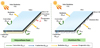 |
Fig. 6 Schematic of heat transfer mechanisms in a PV panel equipped with passive cooling. |
2.5 Thermal model of the PV panel with passive cooling systems
The thermal behavior of the passive cooling layer located on the rear side of the PV module is described employing a general energy conservation equation. The model accounts for both conductive and convective heat transfer, allowing a comprehensive representation of heat transport within the system. The energy balance is expressed as:
 (2)
(2)
The conductive heat flux is governed by Fourier’s law:
 (3)
(3)
Convective heat loss is described using Newton’s law of cooling, where h is the convective heat transfer coefficient. The heat flux depends on the temperature difference between the external fluid temperature Text and the surface temperature (T) [30]:
 (4)
(4)
The convective heat transfer coefficient h is determined using the following empirical relation reported in [31]:
 (5)
(5)
where v is the wind speed in m.s−1.
Stefan-Boltzmann's law is employed to describe the radiative heat transfer, representing the net radiation exchange between the surface of the module and the effective sky temperature [32]:
 (6)
(6)
2.6 Governing equations for cooling using porous media (PU foam)
2.6.1 Moisture transport in porous medium
In the porous foam layer, moisture transport occurs through both water vapor diffusion within the pores and liquid water movement in the porous matrix. For modeling purposes, these mechanisms are represented using a unified mass conservation equation that accounts for vapor transport, liquid flow, and phase interaction effects:
 (7)
(7)
The water vapor mass fraction ωv, representing the proportion of vapor in the gas phase, is defined as:
 (8)
(8)
The transport of water vapor in the gas phase is driven by the pressure gradient in the gaseous flow field, ug, determined from the Brinkman equation, while gw represents its diffusive flux due to binary diffusion in dry air [33]:
 (9)
(9)
The velocity of the liquid phase, ul, within the porous medium is determined using Darcy’s law:
 (10)
(10)
2.6.2 Evaporation flow of water vapour
The evaporative mass flux at the liquid-vapor interface is expressed as:
 (11)
(11)
2.7 Analytical expressions of PV panel performance
The electrical efficiency of the PV module varies with the cell temperature and can be calculated as [34]:
 (12)
(12)
The electrical efficiency of the PV panel varies with the PV temperature, and can be expressed as follows [35]:
 (13)
(13)
where ηSTC is the electrical efficiency under Standard Test Conditions (STC), βSTC is the temperature coefficient of the PV panel (−0.45%/°C as provided by the manufacturer), TPV is the average temperature of the rear surface of the PV module, and TSTC = 25 °C.
3 Results and discussion
This section presents and discusses the numerical results obtained for the reference PV module and the two passive cooling configurations. The analysis is structured as follows: the model validation, the thermal behavior, the electrical performance, and the overall comparison.
3.1 Model validation
The developed COMSOL Multiphysics model is validated using experimental and numerical data reported in the literature for photovoltaic modules equipped with aluminum-fin cooling systems. In particular, the study of Almazhoud et al. [25] is used as the primary benchmark reference for validation.
As shown in Figure 7, a good agreement is observed between the numerical predictions of the present model and the reference data for both the uncooled and Fin-Cooled configurations. The relative deviation remains within 1–4%, confirming the ability of the model to accurately reproduce the transient thermal behavior of the PV system.
The same governing heat transfer mechanisms, including conduction, convection, and radiation, are considered in both the present model and the benchmark study, ensuring physical consistency. In addition, comparable assumptions are adopted regarding material properties, fin geometry, and thermal boundary conditions, where applicable.
Although minor discrepancies may arise due to differences in PV module dimensions, fin configuration, and environmental conditions (solar irradiance, ambient temperature, ambient humidity and wind speed), the proposed model successfully reproduces the same overall thermal trends reported in the literature. The main difference lies in the number of fins (29 in the present study compared to 5 in the reference work), which allows for a more detailed investigation of the effect of fin density on thermal performance.
Overall, the agreement with previous studies confirms the robustness, reliability, and predictive capability of the developed numerical model.
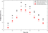 |
Fig. 7 Experimental and numerical evolution of the average rear-surface temperature for reference and cooled PV modules [25]. |
3.2 Thermal behavior under identical operating conditions
The thermal behavior of the PV modules is governed by the balance between the absorbed solar radiation and the heat dissipation through conduction, convection, and radiation. The temperature evolution (Fig. 8) reflects how each cooling strategy modifies this energy balance throughout the day, and the corresponding values are summarized in Table 6.
The Standard Panel exhibits the highest operating temperature because the absorbed solar energy is mainly dissipated through relatively weak natural convection and thermal radiation. Under high irradiance, the heat generation exceeds the dissipation capacity, leading to the progressive heat accumulation.
The Fin-Cooled configuration improves the thermal performance by increasing the effective surface area, which enhances the convective and the radiative heat losses. However, its effectiveness is limited by the internal conduction resistance within the PV module, which restricts the efficient heat transport toward the fins.
In contrast, the Foam-Cooled system introduces an additional evaporative cooling mechanism. When the porous medium is saturated, the part of the thermal energy is consumed as latent heat during water evaporation. This phase-change process significantly increases heat removal capability and stabilizes the temperature of the module, particularly under peak irradiance conditions. As a result, evaporative cooling becomes the dominant heat transfer mechanism, surpassing purely the sensible heat dissipation.
Quantitatively, the average operating temperatures are 50.99 °C, 41.12 °C, and 34.51 °C for the Standard Panel, Fin-Cooled, and Foam-Cooled systems, respectively, corresponding to reductions of 19.35% and 32.32%. These results confirm that phase-change-driven cooling provides a substantially higher thermal regulation capacity compared with extended-surface convective enhancement.
Temperature values of the PV panels at various times of the day under Standard, Foam-Cooled, and Fin-Cooled configurations.
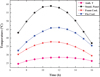 |
Fig. 8 PV panel temperature variations throughout the day: Ambient Temperature, Standard Panel, Foam Cooled, and Fin Cooled. |
3.3 Electrical performance under thermal regulation
The electrical performance of PV modules is strongly dependent on the temperature. An increase in the PV temperature reduces the open-circuit voltage due to enhanced carrier recombination, which leads to a lower power output and efficiency.
3.3.1 Power output
The electrical power output is calculated using equation (12). As shown in Figure 9, all the configurations follow the typical PV daily profile, characterized by an increase in the morning, a peak around 11:00 h, and a decrease in the afternoon.
Both the cooling strategies improve the electrical performance compared with the uncooled module. The Foam-Cooled method achieves the highest average power output (71.5 W), followed by the Fin-Cooled configuration (69.9 W), while the Standard Panel records 65.2 W. This corresponds to average gains of 6.3 W (Foam-Cooled) and 4.7 W (Fin-Cooled), respectively.
These improvements are directly attributed to reduced thermal losses and improved voltage retention at elevated irradiance levels.
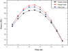 |
Fig. 9 Electrical power of the PV modules under: Standard, Foam, and Fin Cooling configurations. |
3.3.2 Electrical efficiency
Figure 10 presents the temporal evolution of the electrical efficiency for the three configurations.
A slight decrease in the efficiency is observed around midday, mainly due to the increase in the PV temperature during the peak solar irradiance conditions. In this regime, thermal losses become more significant, leading to a reduction in the open-circuit voltage and the overall conversion efficiency. Compared with the Standard Panel, both cooling techniques consistently improve efficiency throughout the day by limiting the temperature rise of the PV module.
However, the Foam-Cooled method provides a more stable thermal environment, resulting in higher and more sustained efficiency levels. The average efficiencies are 13.15% for the Standard Panel, 13.92% for the Fin-Cooled system, and 14.33% for the Foam-Cooled configuration, respectively.
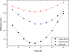 |
Fig. 10 Electrical efficiency of PV panels: Standard, Foam Cooling, and Fin Cooling. |
3.3.3 Overall performance comparison
Figure 11 presents the relative improvement in the electrical efficiency of the cooling configurations compared with the standard PV module. The efficiency gain is calculated using equation (14):
 (14)
(14)
The results show a clear diurnal variation, with higher efficiency gains observed during periods of high solar irradiance and elevated ambient temperature. This confirms the strong coupling between thermal and electrical behavior in PV systems. On average, the Foam-Cooled and Fin-Cooled configurations achieve efficiency improvements of 8.49% and 5.10%, respectively. The superior performance of the foam system is attributed to its enhanced thermal regulation through evaporative cooling.
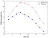 |
Fig. 11 Efficiency gain of PV panels: Standard, Foam Cooling, and Fin Cooling. |
4 Comparative analysis
Table 7 compares the proposed passive cooling configurations with previously reported PV cooling techniques in terms of the temperature reduction and the electrical performance enhancement.
The aluminum-fin system achieves a temperature reduction of 9.87 °C (19.35%), while the PU foam configuration reaches 16.48 °C (32.32%). The corresponding improvements in the electrical efficiency are 5.10% and 8.49%, respectively.
It should be noted that the studies included in this comparison involve different PV systems, cooling geometries, environmental conditions, irradiance levels, and evaluation methodologies. Therefore, the comparison is not fully normalized, and direct quantitative ranking between techniques should be interpreted with caution.
Despite these differences, the obtained results remain within the range of values reported in the literature for similar passive cooling strategies, confirming consistency with previously published studies.
From a physical perspective, evaporative cooling systems generally provide higher thermal and electrical performance improvements compared to fin-based heat sink systems, which is also observed in the present work.
Overall, the comparative analysis confirms that the proposed cooling configurations follow the same trends reported in the literature on PV thermal management, without implying performance superiority.
The level of agreement with previous studies is considered qualitative in terms of trends and semi-quantitative in terms of order of magnitude, due to differences in the configurations of the systems, boundary conditions, and modeling assumptions.
Comparative performance of passive cooling strategies for PV panels including the present study.
5 Conclusion
This study investigated the thermal and the electrical performance of a PV module equipped with two passive cooling methods, namely a water-saturated polyurethane (PU) foam layer and aluminum fins attached to the rear surface. The analysis was carried out using three-dimensional transient numerical simulations in COMSOL Multiphysics under realistic environmental conditions.
The numerical model has been validated against experimental data reported in the literature, showing good agreement and confirming its ability to accurately reproduce the transient thermal behavior of PV systems, thereby ensuring the reliability of the simulation framework.
The results demonstrate a strong dependence of the PV performance on the operating temperature. The PU foam configuration provides the most effective thermal regulation, reducing the average module temperature from 50.99 °C to 34.51 °C (32.32%). This thermal improvement leads to an increase in the electrical power output from 65.2 W to 71.5 W, while the efficiency is improved from 13.15% to 14.33%. The Fin-based configuration also enhances the performance, although to a lesser extent due to its reliance mainly on the convective heat transfer enhancement. This superior performance can be attributed to the additional evaporative cooling mechanism in the foam layer, where latent heat absorption during the water phase change significantly increases the heat removal compared to the purely convective or conductive cooling.
Overall, the findings confirm that passive cooling strategies can significantly improve the PV performance by reducing the thermal losses without requiring external energy input. Among the investigated solutions, the PU Foam-based configuration demonstrates superior thermo-electrical performance under the studied conditions.
From a practical application standpoint, the proposed cooling configurations are particularly suitable for real-world PV systems due to their simplicity, low cost, passive operation, and absence of external energy consumption. Their structural design enables easy integration into existing PV modules or incorporation during the manufacturing process, making them highly relevant for deployment in hot and high-irradiance environments where efficient thermal management is essential to maintain stable performance.
It should be noted that the present study is based on numerical simulations under controlled conditions. Real-world effects such as dust accumulation, material aging, wind variability, and seasonal variations have not been considered. In addition, no economic or lifecycle assessment has been performed in this work.
Nomenclature
A: Area of the PV panel (m2)
CP: Specific heat Capacity at constant pressure (J.kg−1.K−1)
Cv: Vapor concentration in the bulk air (mol.m−3)
CSat: Saturated vapour concentration at the interface (mol.m−3)
Deff: Effective vapor diffusivity in the porous medium (m2.s−1)
gevap: Evaporative mass flux (kg.m−2.s−1)
glc: Capillary liquid mass flux (kg.m−2.s−1)
G: Volumetric mass source (kg.m−3.s−1)
h: Convective heat transfer coefficient (W.m−2.K−1)
I: Incident solar irradiance (W.m− 2)
k: Thermal conductivity (W.m−1.K−1)
keff: Effective thermal conductivity of the porous medium (W.m−1.K−1)
krl: Permeability of liquid water (m2)
K: Mass transfer coefficient (m.s−1)
MV: Molar mass of water vapor (kg.mol−1)
P: Electrical power output (W)
PA: Absolute pressure of moist air (Pa)
q: Heat flux (W.m−2)
Q: Volumetric heat source (W.m−3)
Qevap: Heat source due to evaporation (W.m−3)
Qted: Volumetric thermal energy dissipation term (W.m−3)
Sl: Liquid saturation
T: Temperature (°C)
ug: Gas phase velocity (m.s−1)
ul: Liquide phase velocity (m.s−1)
Greek symbols
βSTC: Temperature coefficient of electrical efficiency (K−1)
ε: Surface emissivity
εp: Porosity of the porous medium
η: Electrical efficiency of the PV module
μl: Dynamic viscosity of the liquid phase (Pa.s)
ρ: Density (kg.m−3)
σ: Stefan-Boltzmann constant (W.m⁻2.K⁻⁴)
φw: Relative humidity at the panel surface
ωv: Water vapor mass fraction
θS: Solid volume fraction
∇: Gradient operator
Subscripts
amb: Ambient
eff: Effective
evap: Evaporation
g: Gas phase
l: Liquid phase
P: Porous medium
PV: Photovoltaic panel
S: Solid matrix
STC: Standard Test Conditions
V: Vapor
Acknowledgments
Mrs. Wilhelmina Logerais, a native English speaker, is heartily thanked for re-reading this paper.
Funding
All authors declare that they have no known financial interests or personal relationships that could have influenced the work reported in this paper.
Conflicts of interest
The authors declare no potential conflicts of interest.
Data availability statement
The data supporting this article are not publicly available.
Author contribution statement
M. ALMAZHOUD: Data curation, Formal analysis, Resources, Validation, Writing – original draft; K. CHNINI: Investigation, Resources; H. FARHAT: Methodology, Writing – review & editing; M. KARKRI and P.O. LOGERAIS: Investigation, Visualization; M. ABDOU TANKARI: Methodology, Formal analysis.
References
- J. Hu, W. Chen, D. Yang, B. Zhao, H. Song, B. Ge, Energy performance of ETFE cushion roof integrated photovoltaic/thermal system on hot and cold days, Appl. Energy 173, 40 (2016). https://doi.org/10.1016/j.apenergy.2016.03.111 [Google Scholar]
- I. Al-Masalha, A.S. Alsabagh, O. Badran, N. Alkawaldeh, T.M. Abu-Rahmeh, A. Al Alawin, Improving photovoltaic module efficiency using water sprinklers, air fans, and combined cooling systems, EPJ Photovolt. 15, 41 (2024). https://doi.org/10.1051/epjpv/2024037 [Google Scholar]
- I. Cornago et al., New approach of PV and thermal modeling to develop feasible cooling solutions for PV in buildings, EPJ Photovolt. 16, 19 (2025). https://doi.org/10.1051/epjpv/2025007 [Google Scholar]
- A. Hamzat, A. Sahin, M. Omisanya, L. Alhems, Advances in PV and PVT cooling technologies: a review, Sustain. Energy Technol. Assess. 47, 101360 (2021). https://doi.org/10.1016/j.seta.2021.101360 [Google Scholar]
- S. Nižetić, F. Grubišić-Čabo, I. Marinić-Kragić, A.M. Papadopoulos, Experimental and numerical investigation of a backside convective cooling mechanism on photovoltaic panels, Energy 111, 211 (2016). https://doi.org/10.1016/j.energy.2016.05.103 [CrossRef] [Google Scholar]
- A. Kladas, B. Herteleer, J. Cappelle, Blind PV temperature model calibration, EPJ Photovolt. 14, 28 (2023). https://doi.org/10.1051/epjpv/2023021 [Google Scholar]
- I. Masalha, S.U. Masuri, O. Badran, A. Alahmer, A multi-method approach to investigating porous media cooling for enhanced thermal performance of photovoltaic panels: exploring the effects of porosity, flow rates, channel design, and coolant types, Int. J. Thermofluids 27, 101165 (2025). https://doi.org/10.1016/j.ijft.2025.101165 [Google Scholar]
- A.H. Shiravi, M. Firoozzadeh, M. Lotfi, Experimental study on the effects of air blowing and irradiance intensity on the performance of photovoltaic modules, using central composite design, Energy 238, 121633 (2022). https://doi.org/10.1016/j.energy.2021.121633 [Google Scholar]
- I. Masalha, A. Alahmer, A.S. Alsabagh, O. Badran, S.U. Masuri, Predictive analysis of porous media–cooled photovoltaic panels using gradient-boosting machine learning models, Renew. Energy 260, 125121 (2026). https://doi.org/10.1016/j.renene.2025.125121 [Google Scholar]
- K.T. Alao et al., Multi-method cooling strategies for photovoltaic systems: a comprehensive review of passive, active, and AI-optimized hybrid techniques, Multiscale Multidiscip. Model. Exp. Des. 8, 365 (2025). https://doi.org/10.1007/s41939-025-00941-w [Google Scholar]
- L. Tang, Y. Zhou, S. Zheng, G. Zhang, Exergy-based optimisation of a phase change materials integrated hybrid renewable system for active cooling applications using supervised machine learning method, Sol. Energy 195, 514 (2020). https://doi.org/10.1016/j.solener.2019.11.067 [Google Scholar]
- F.F. Ahmad, C. Ghenai, A.K. Hamid, O. Rejeb, M. Bettayeb, Performance enhancement and infra-red (IR) thermography of solar photovoltaic panel using back cooling from the waste air of building centralized air conditioning system, Case Stud. Therm. Eng. 24, 100840 (2021). https://doi.org/10.1016/j.csite.2021.100840 [Google Scholar]
- H.A. Kazem, A.H.A. Al-Waeli, M.T. Chaichan, K. Sopian, Numerical and experimental evaluation of nanofluids based photovoltaic/thermal systems in Oman: using silicone-carbide nanoparticles with water-ethylene glycol mixture, Case Stud. Therm. Eng. 26, 101009 (2021). https://doi.org/10.1016/j.csite.2021.101009 [Google Scholar]
- F. AlAmri, G. AlZohbi, M. AlZahrani, M. Aboulebdah, Analytical modeling and optimization of a heat sink design for passive cooling of solar PV panel, Sustainability 13, 3490 (2021). https://doi.org/10.3390/su13063490 [Google Scholar]
- M. Faheem, M. Abu Bakr, M. Ali, M.A. Majeed, Z.M. Haider, M.O. Khan, Evaluation of efficiency enhancement in photovoltaic panels via integrated thermoelectric cooling and power generation, Energies 17, 2590 (2024). https://doi.org/10.3390/en17112590 [Google Scholar]
- D. Mazzeo, L.P.M. Colombo, S. Leva, A review of photovoltaic cooling with phase change materials: technical advances, modeling approaches, efficiency gains and economic/environmental impact, Appl. Therm. Eng. 280, 128222 (2025). https://doi.org/10.1016/j.applthermaleng.2025.128222 [Google Scholar]
- Y. Gao, D. Wu, Z. Dai, C. Wang, B. Chen, X. Zhang, A comprehensive review of the current status, developments, and outlooks of heat pipe photovoltaic and photovoltaic/thermal systems, Renew. Energy 207, 539 (2023). https://doi.org/10.1016/j.renene.2023.03.039 [Google Scholar]
- K.T. Alao et al., Passive cooling of photovoltaic panels using radiative paints and metal foam fins: a critical review of mechanisms, materials, and performance metrics, Meas. Energy 8, 100076 (2025). https://doi.org/10.1016/j.meaene.2025.100076 [Google Scholar]
- P.M. Arivazhagan, S. Mathappan, R. Prabakaran, M.L. Dhasan, Water film cooling of PV panels for maximizing compressor running time in solar refrigeration, Appl. Therm. Eng. 299, 131196 (2026). https://doi.org/10.1016/j.applthermaleng.2026.131196 [Google Scholar]
- G.S. Wahile, S.D. Londhe, Experimental study on evaporative cooling of photovoltaic panel using cotton wick, Sustain. Waste Manag. Pract. 2, 387 (2025). https://doi.org/10.1007/978-981-95-1442-7_31 [Google Scholar]
- K. Srithar, K. Akash, R. Nambi, M. Vivar, R. Saravanan, Enhancing photovoltaic efficiency through evaporative cooling and a solar still, Sol. Energy 265, 112134 (2023). https://doi.org/10.1016/j.solener.2023.112134 [Google Scholar]
- T. Chea, T. Deethayat, T. Kiatsiriroat, A. Asanakham, Experiment and model of a photovoltaic module with evaporative cooling, Results Eng. 19, 101290 (2023). https://doi.org/10.1016/j.rineng.2023.101290 [Google Scholar]
- I. Masalha, O. Badran, S.U. Masuri, R. Alkhazaleh, A.S. Alsabagh, A. Alahmer, Experimental Investigation of flint-based porous media cooling for enhanced photovoltaic performance, Energy Sources Part A: Recovery Util. Environ. Eff. 47, 559158 (2025). https://doi.org/10.1080/15567036.2025.2559158 [Google Scholar]
- D.M.N. Mahmood, I.M.A. Aljubury, Experimental investigation of a hybrid photovoltaic evaporative cooling (PV/EC) system performance under arid conditions, Results Eng. 15, 100618 (2022). https://doi.org/10.1016/j.rineng.2022.100618 [Google Scholar]
- M. Almazhoud, H. Dahman, M. Khelil, H. Farhat, Experimental assessment of passive rear-fin cooling on photovoltaic module performance, Sol. Energy 313, 114631 (2026). https://doi.org/10.1016/j.solener.2026.114631 [Google Scholar]
- A. Gupta, S.S. Chougule, S.K. Saha, Porous cooling and thermoelectric generation in concentrated photovoltaic thermal systems, Appl. Therm. Eng. 280, 128451 (2025). https://doi.org/10.1016/j.applthermaleng.2025.128451 [Google Scholar]
- C. Pomares-Hernández, E.A. Zuluaga-García, G.E. Escorcia Salas, C. Robles-Algarín, J. Sierra Ortega, Computational modeling of passive and active cooling methods to improve PV panels efficiency, Appl. Sci. 11, 11370 (2021). https://doi.org/10.3390/app112311370 [Google Scholar]
- F. Nicoletti, M.A. Cucumo, V. Ferraro, D. Kaliakatsos, A. Gigliotti, A thermal model to estimate PV electrical power and temperature profile along panel thickness, Energies 15, 7577 (2022). https://doi.org/10.3390/en15207577 [Google Scholar]
- W.C. Swinbank, Long‐wave radiation from clear skies, Q. J. R. Meteorol. Soc. 89, 339 (1963). https://doi.org/10.1002/qj.49708938105 [Google Scholar]
- G. Maragkos, T. Beji, Review of convective heat transfer modelling in CFD simulations of fire-driven flows, Appl. Sci. 11, 5240 (2021). https://doi.org/10.3390/app11115240 [Google Scholar]
- Y. Hayakawa, D. Sato, N. Yamada, Measurement of the convective heat transfer coefficient and temperature of vehicle-integrated photovoltaic modules, Energies 15, 4818 (2022). https://doi.org/10.3390/en15134818 [Google Scholar]
- L. Lévesque, Law of cooling, heat conduction and Stefan-Boltzmann radiation laws fitted to experimental data for bones irradiated by CO2 laser, Biomed. Opt. Express 5, 701 (2014). https://doi.org/10.1364/BOE.5.000701 [Google Scholar]
- D. Alezi et al., Metal–organic framework-based atmospheric water harvesting for enhanced photovoltaic efficiency and sustainability, Mater. Adv. 5, 4660 (2024). https://doi.org/10.1039/d3ma00960b [Google Scholar]
- Z. Kaneesamkandi, M.J. Almalki, A. Sayeed, Z.A. Haidar, Passive cooling of PV modules using heat pipe thermosiphon with acetone: experimental and theoretical study, Appl. Sci. 13, 1457 (2023). https://doi.org/10.3390/app13031457 [Google Scholar]
- S. Dubey, J.N. Sarvaiya, B. Seshadri, Temperature dependent photovoltaic (PV) efficiency and its effect on PV production in the world – a review, Energy Procedia 33, 311 (2013). https://doi.org/10.1016/j.egypro.2013.05.072 [CrossRef] [Google Scholar]
- M. Lucas, F.J. Aguilar, J. Ruiz, C.G. Cutillas, A.S. Kaiser, P.G. Vicente, Photovoltaic evaporative chimney as a new alternative to enhance solar cooling, Renew. Energy 111, 26 (2017). https://doi.org/10.1016/j.renene.2017.03.087 [Google Scholar]
- Z.A. Haidar, J. Orfi, Z. Kaneesamkandi, Photovoltaic panels temperature regulation using evaporative cooling principle: detailed theoretical and real operating conditions experimental approaches, Energies 14, 145 (2020). https://doi.org/10.3390/en14010145 [Google Scholar]
- A.M. Elbreki, A.F. Muftah, K. Sopian, H. Jarimi, A. Fazlizan, A. Ibrahim, Experimental and economic analysis of passive cooling PV module using fins and planar reflector, Case Stud. Therm. Eng. 23, 100801 (2021). https://doi.org/10.1016/j.csite.2020.100801 [Google Scholar]
- F. Grubišić-Čabo, S. Nižetić, E. Giama, A. Papadopoulos, Techno-economic and environmental evaluation of passive cooled photovoltaic systems in mediterranean climate conditions, Appl. Therm. Eng. 169, 114947 (2020). https://doi.org/10.1016/j.applthermaleng.2020.114947 [Google Scholar]
- A. El Mays et al., Improving photovoltaic panel using finned plate of aluminum, Energy Procedia 119, 812 (2017). https://doi.org/10.1016/j.egypro.2017.07.103 [Google Scholar]
- F. Grubišić-Čabo, S. Nižetić, C. Duje, I. Marinic-Kragic, A. Papadopoulos, Experimental investigation of the passive cooled free-standing photovoltaic panel with fixed aluminum fins on the backside surface, J. Clean. Prod. 176, 119 (2018). https://doi.org/10.1016/j.jclepro.2017.12.149 [Google Scholar]
- D. Vittorini, R. Cipollone, Fin-cooled photovoltaic module modeling – performances mapping and electric efficiency assessment under real operating conditions, Energy 167, 159 (2019). https://doi.org/10.1016/j.energy.2018.11.001 [Google Scholar]
Cite this article as: Mariem Almazhoud, Khalil Chnini, Habib Farhat, Mustapha Karkri, Pierre Olivier Logerais, Mahamadou Abdou Tankari, Numerical investigation of passive cooling strategies for photovoltaic modules using recycled polyurethane foam and aluminum fins, EPJ Photovoltaics 17, 28 (2026), https://doi.org/10.1051/epjpv/2026021
All Tables
Temperature values of the PV panels at various times of the day under Standard, Foam-Cooled, and Fin-Cooled configurations.
Comparative performance of passive cooling strategies for PV panels including the present study.
All Figures
|
Fig. 1 Photographs of experimental components used as reference for numerical modeling. |
| In the text | |
|
Fig. 2 Schematic representation of the modeled photovoltaic (PV) configurations: (a) Standard Panel, (b) PU Foam-Cooled Panel, (c) Fin-Cooled Panel. |
| In the text | |
|
Fig. 3 Mesh layout of the PV module. |
| In the text | |
|
Fig. 4 Temporal evolution of ambient temperature and solar irradiation. |
| In the text | |
|
Fig. 5 Variations of the ambient humidity and wind speed over time. |
| In the text | |
|
Fig. 6 Schematic of heat transfer mechanisms in a PV panel equipped with passive cooling. |
| In the text | |
|
Fig. 7 Experimental and numerical evolution of the average rear-surface temperature for reference and cooled PV modules [25]. |
| In the text | |
|
Fig. 8 PV panel temperature variations throughout the day: Ambient Temperature, Standard Panel, Foam Cooled, and Fin Cooled. |
| In the text | |
|
Fig. 9 Electrical power of the PV modules under: Standard, Foam, and Fin Cooling configurations. |
| In the text | |
|
Fig. 10 Electrical efficiency of PV panels: Standard, Foam Cooling, and Fin Cooling. |
| In the text | |
|
Fig. 11 Efficiency gain of PV panels: Standard, Foam Cooling, and Fin Cooling. |
| In the text | |
Current usage metrics show cumulative count of Article Views (full-text article views including HTML views, PDF and ePub downloads, according to the available data) and Abstracts Views on Vision4Press platform.
Data correspond to usage on the plateform after 2015. The current usage metrics is available 48-96 hours after online publication and is updated daily on week days.
Initial download of the metrics may take a while.