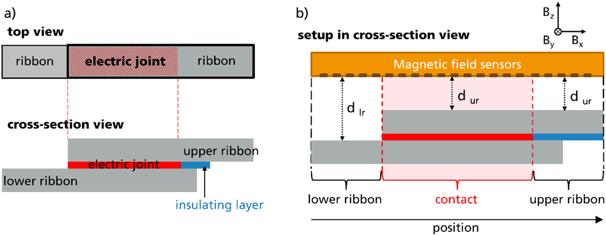
Fig. 1

Download original image
Sample setup (a) drawn in top and cross-section view where the electrical joint between the upper and lower ribbon is red colored. (b) represents the measurement setup with the magnetic field line sensor parallel and centered to the test structure. Characteristic sample areas under investigation are indicated by brackets and distances from the sensor to the lower ribbon (dlr) or upper ribbon (dur).
Current usage metrics show cumulative count of Article Views (full-text article views including HTML views, PDF and ePub downloads, according to the available data) and Abstracts Views on Vision4Press platform.
Data correspond to usage on the plateform after 2015. The current usage metrics is available 48-96 hours after online publication and is updated daily on week days.
Initial download of the metrics may take a while.


